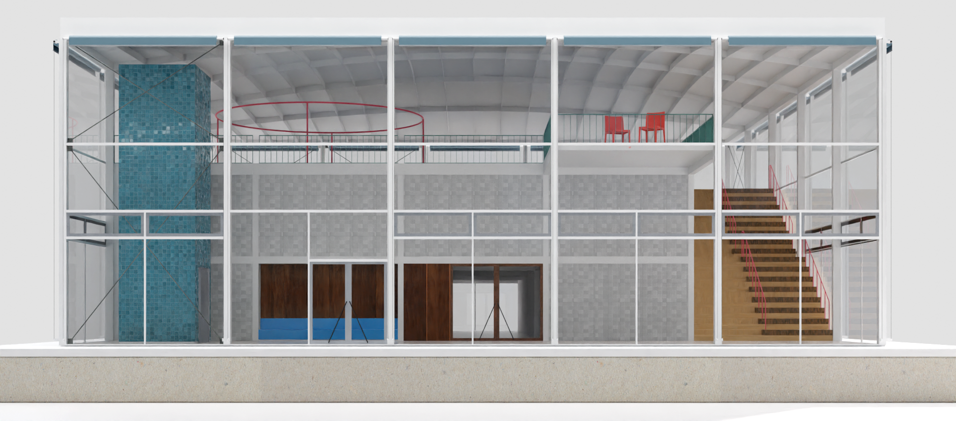
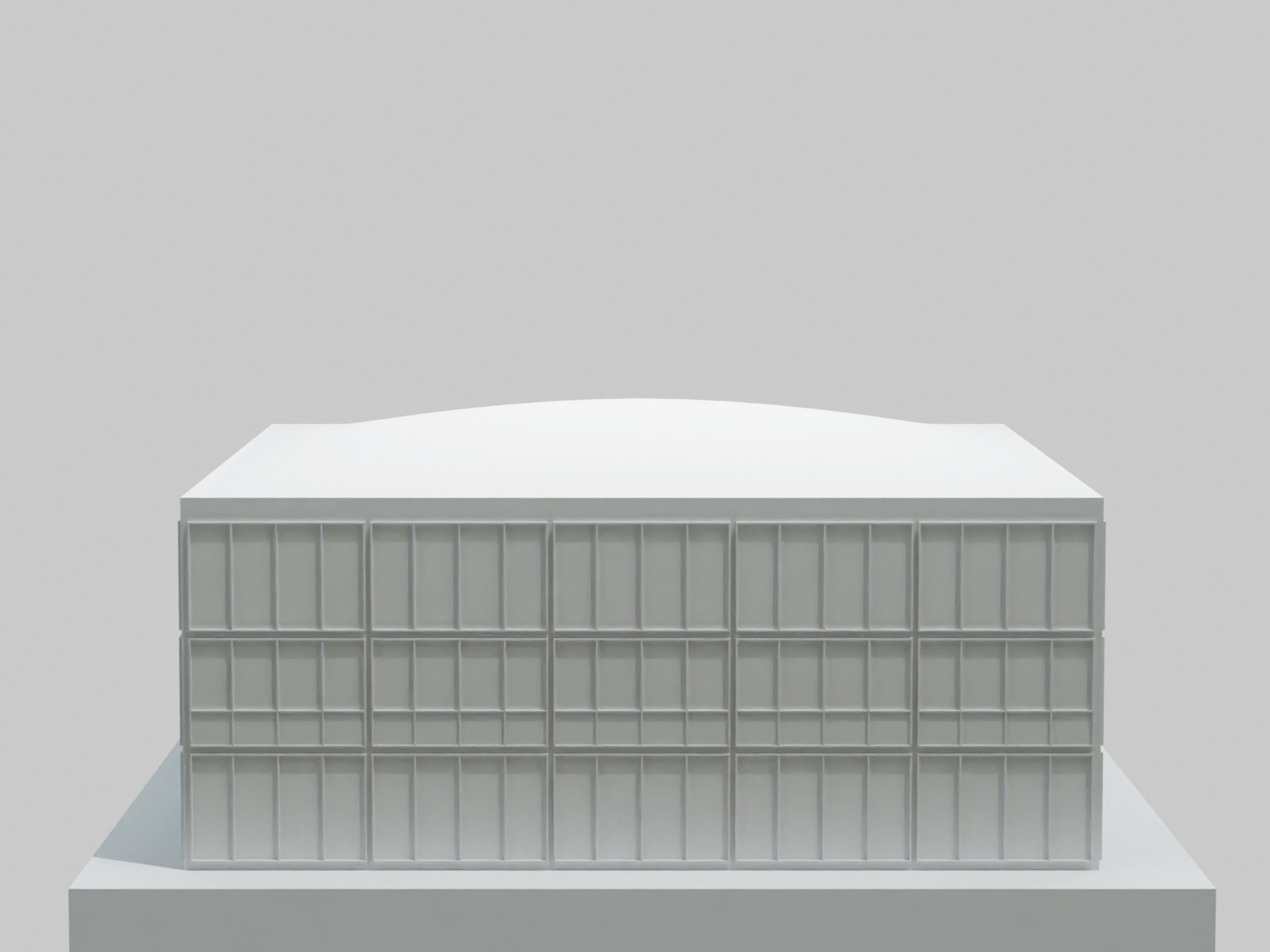
Model Perspective
Concept
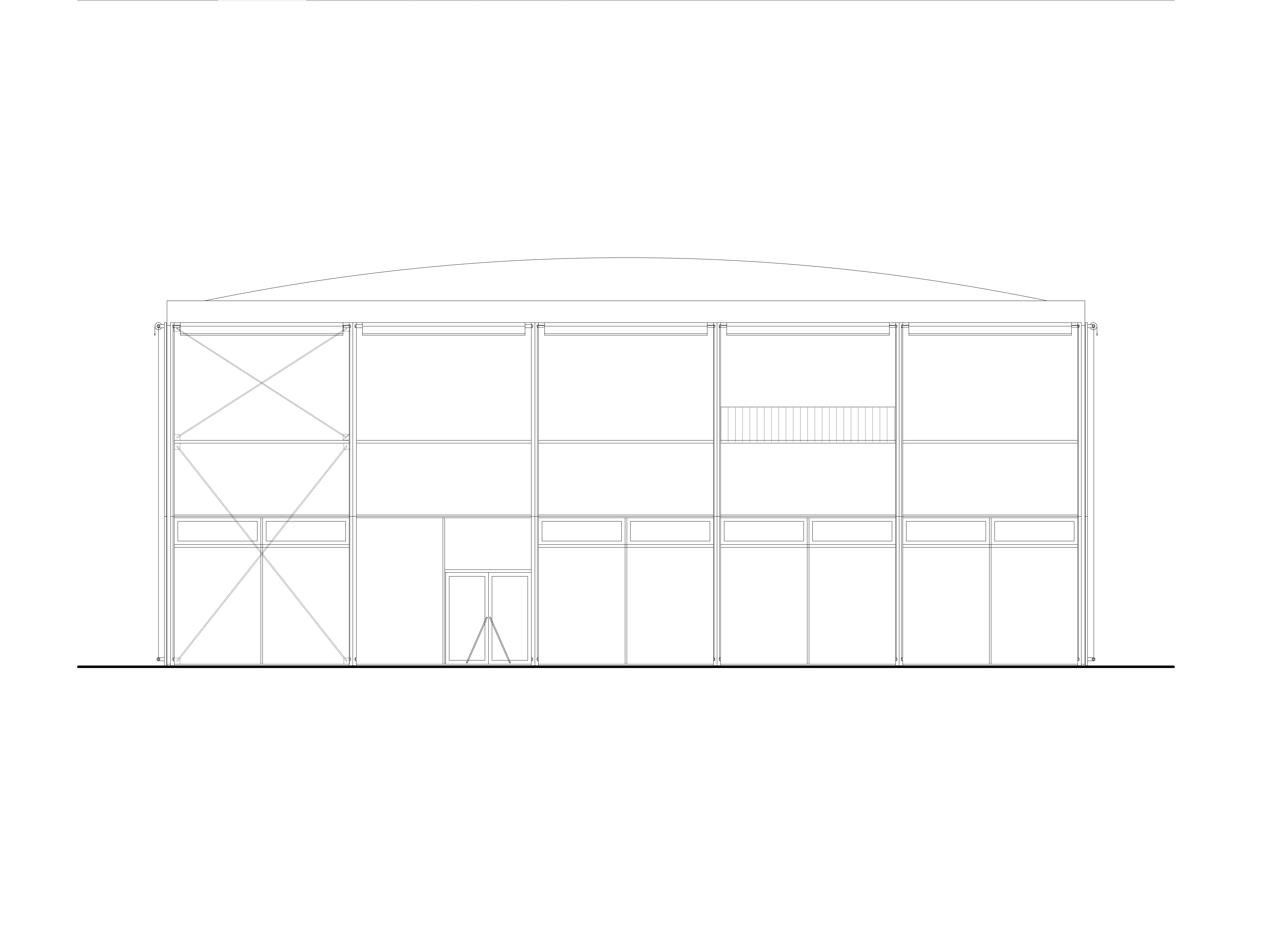
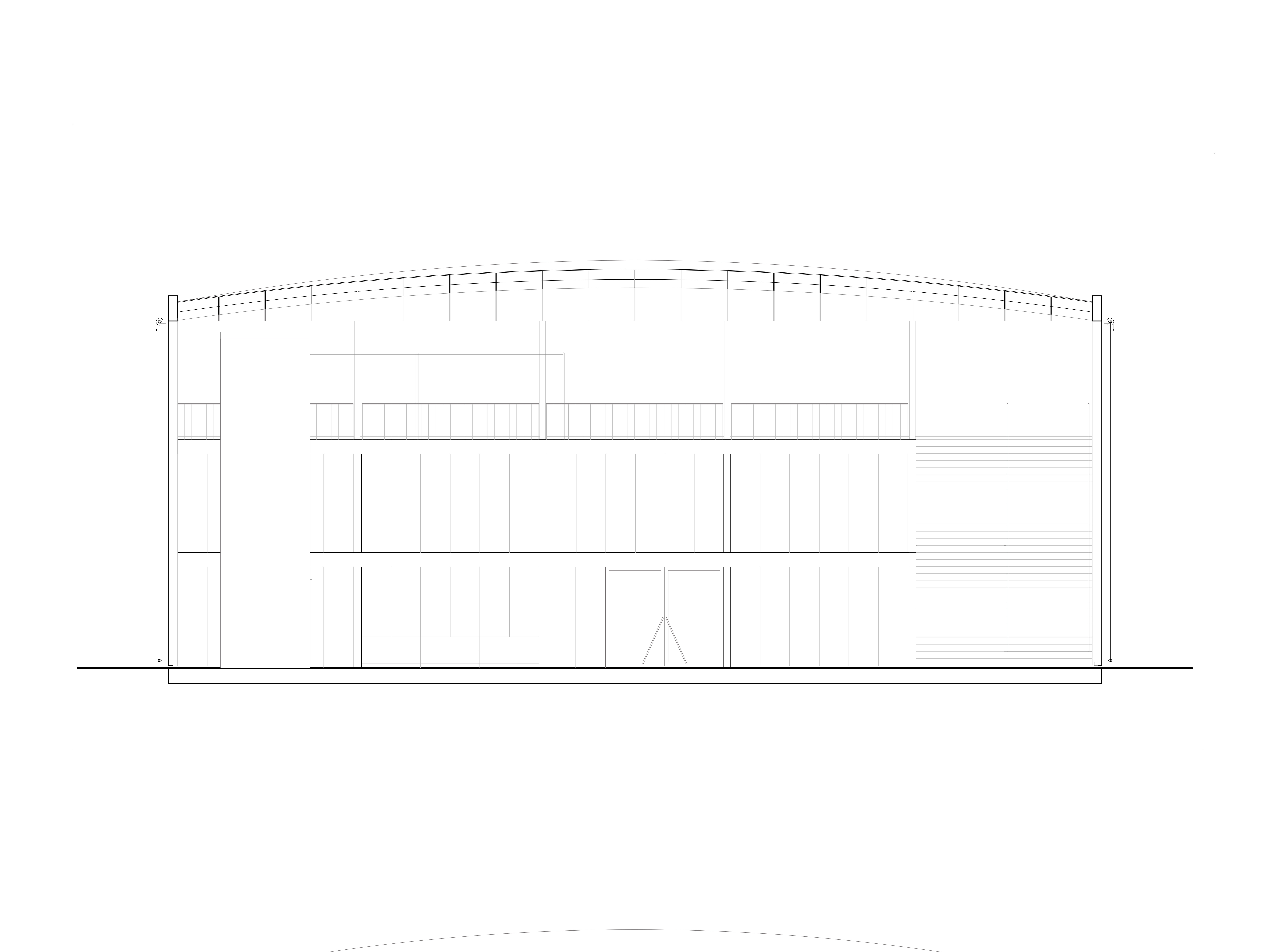
This building features a clear-span structure with a glass façade and an exposed steel frame, creating an open interior that emphasizes connection between inside and outside. A tiled blue core runs through both levels and serves as a visual anchor, while a mezzanine level looks out over the main floor and provides flexible space for work or gathering.
A wide staircase with minimal railings connects the floors and enhances the sense of flow. Subtle touches of color, like the red chairs and railings, stand out against a calm backdrop of concrete, glass, and wood finishes.
The design takes inspiration from modernist architecture, focusing on transparency, functional use of space, and simple, honest materials. The result is a building that can adapt to different uses over time while maintaining a clear sense of structure and purpose.
Lightweight Steel Dome
The addition of cross-bracing elements significantly improves structural performance by reducing maximum deformation and achieving a more uniform deflection distribution. In the original unbraced configuration, deformations reached -23.9 mm at edge supports and up to -10.6 mm in central grid members, indicating substantial lateral displacement and inadequate stiffness, particularly along the perimeter. With cross-bracing, maximum deformation at the edges decreased to -10.3 mm (a 57% reduction), while central deformations dropped to -1.7 mm to -2.9 mm, reflecting a 75-83% improvement. These changes demonstrate increased lateral stiffness and improved resistance to bending and shear deformations, as the bracing redistributes loads more effectively, reducing stress concentrations and ensuring a more uniform deformation profile. This enhances load-bearing capacity and makes the structure more robust.
Force Distributions
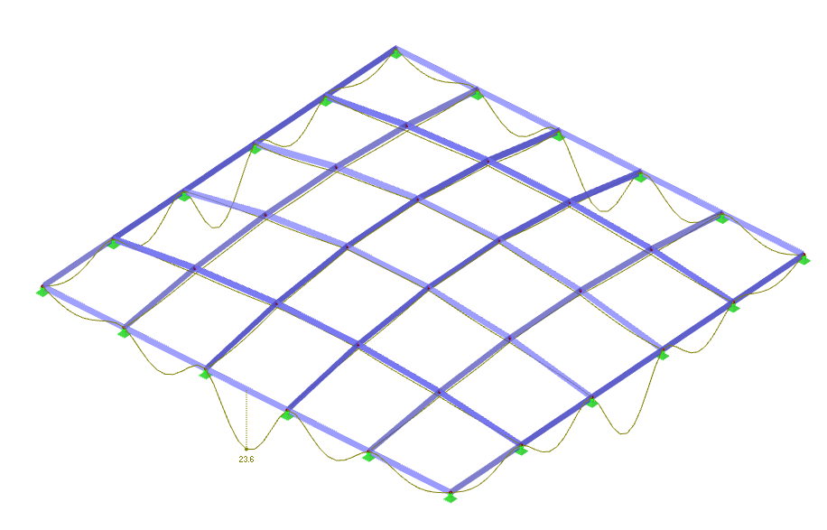
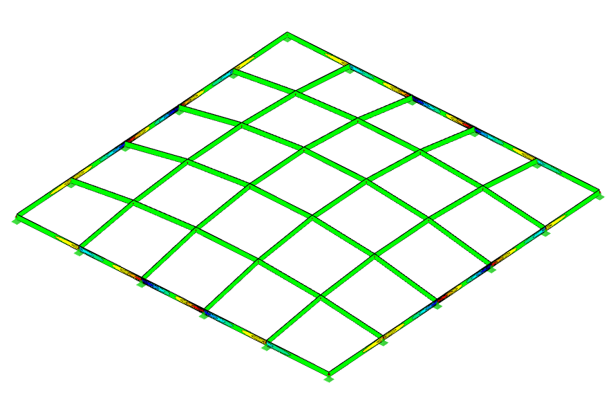
Deformation
This diagram shows the global deformations of the dome-like grid shell under the applied load. The maximum deflection of about 23.6 mm occurs at the perimeter, where the edge beams sag due to insufficient horizontal restraint. The interior grid remains relatively stable thanks to its form-active geometry, while the outward thrust causes the unsupported edges to drop. This highlights the need for additional edge stiffening or bracing to fully control perimeter deformations and maintain the intended shell action.
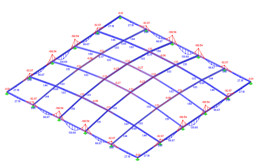
Internal Forces My
The second image displays the bending moments (M‑y) in the members. Negative moments develop near the supports while positive bending appears within the spans, following the typical pattern for a continuous, rigidly connected grid. The dome’s geometry helps to reduce bending overall, but edge members still carry the highest bending moments and need careful design.
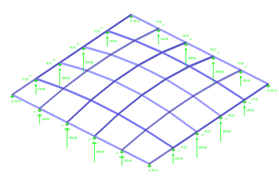
Support Reactions
This diagram shows the support reactions for the dome-like grid shell without cross bracing. The structure channels most vertical loads to the interior supports, with significant reactions around 450 kN, while the perimeter supports carry smaller vertical and horizontal components. This reaction pattern confirms that the curved geometry alone efficiently directs loads and stabilizes the system by transforming vertical forces into axial compression and horizontal thrust, which must be resisted by the supports and edge beams.
Normal Forces N
The first diagram shows the internal axial forces in the grid structure under a representative load case. The members experience uniform compression, with forces around –20 kN, indicating efficient load transfer through the frame towards the supports. This pattern suggests the grid acts as a braced system, distributing vertical loads primarily via axial action.
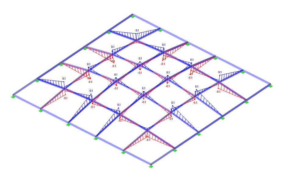
Moment
The third diagram illustrates the horizontal deformations (u‑X) of the structure. The displacements are minimal, with a maximum of ±0.1 mm, confirming that the dome shape and cross bracing effectively stabilize the system. This ensures that lateral sway is controlled and the curved grid performs as a stiff, self-supporting shell.
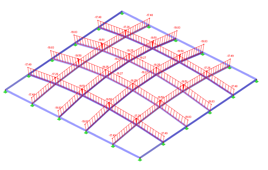
Stresses
This diagram shows the distribution of shear stress τz in the grid shell under the given load case. The structure’s dome-like geometry ensures that most members primarily carry axial forces, resulting in minimal shear stress in the interior. Higher shear stresses appear near the edges and nodes, where bending and force flow changes generate local transverse shear. The balanced distribution confirms that the grid shell efficiently channels loads to its supports while keeping internal shear within manageable limits.